<< Previous | Outline | Next >>
Corrections to Tested Performance: Sensible Capacity
- Sensible / Total
- The sensible/total capacity ratio is determined by an iterative technique based on the apparatus dew-point and bypass factor method (ADP/BPF). This method is dependent on the S/T ratio (at rating conditions), air flow rate, total capacity, ODB, EWB, and EDB.
- This iterative technique can be represented functionally:
S/TADP = S/TADP(S/Trated, Flow, Capacity, ODB, EWB, EDB)
- Sensible capacity is the product of this ratio and the total capacity.
- SC = S/TADP * TC(ODB, EWB)
Discussion
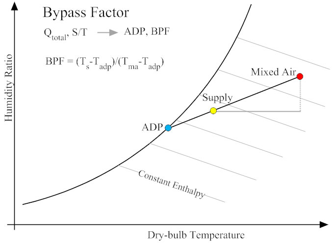
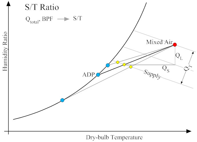
In making predictions of sensible capacity at conditions differing from ARI test conditions, the calculation engine makes use of the iterative apparatus dew-point and bypass factor method. This method acts to first characterize the cooling coil with a bypass factor based on its sensible and total capacity at ARI test conditions (see Figure 1a). This bypass factor can then be used to predict the sensible-to-total ratio of the coil at entering conditions, flow rates, and total capacity levels, other than those at ARI test conditions (see Figure 1b).
There is a separate system performance calculation page that serves to dynamically illustrate the ADP/BPF method described here. The results shown in the "S/T" columns are the result of the iterative calculation using the ADP/BPF method. Of the three variations of this S/T result, the S/T (BP-EP) is the one actually used in calculation engine. This version has algorithmic similarities with the form of the method that is used in the EnergyPlus system simulator.
The letters "S" stands for supply, "E" for entering, and "O" for outside, "HR" for humidity ratio, "DB" for dry-bulb, and "WB" for wet-bulb. The "BPF" factor, shown at the top row of the second table, is the calculated bypass factor at the user-entered ARI conditions. All columns to the right of and including the "BPF" column are calculated with the ADP/BPF method.
To run the calculation, enter system performance data (at ARI test conditions) in the text boxes in the top row and then press the "Submit" button. This produces a table of predicted coil performance for a variety of entering conditions. The second row of inputs allows you to change the capacity level and air flow rate that the projection table is based on (by default, these values are left equal to the ARI conditions specified in the first row of inputs).